In years gone by the primary interface used for communicating data was the serial interface. Its name stems from the fact that data was communicated one bit at a time, one bit after another - that is, serially. The alternative was a parallel interface, where all the bits making up, say, a byte would be communicated in parallel. In principle a parallel interface is faster, but also more expensive since it needs one circuit for every bit, whereas serial needs a single circuit to communicate one bit at a time. Most current data communication technologies use serial transmission: USB, Ethernet via coax, Firewire, Ethernet via UTP at 100Mbps or less, etc. Where the water is muddied somewhat is at the faster communication rates: Ethernet via UTP at gigabit speeds tend to transmit two bits in parallel...
For many, many years the most popular standard was RS-232 (that is Recommended Standard number 232 of the Electronics Industries Association or EIA). The standard was issued in a number of versions, with B, C and D suffixed to the later versions. However, industry did not see the need to proceed beyond the C-version, and RS-232-C was therefore the standard used in practice.
Despite being a standard one often spent countless hours trying to get two pieces of equipment to talk to one another. Some of the problems stemmed from the fact that few vendors' products really complied with the standard. Other problems often stemmed from the way the communication interfaces were used: The standard really specifies a way to interface a computer to a peripheral unit. Clearly, the more interesting option was to get two computers to talk to one another.
Given such a myriad of problems every self-respecting data communication fan had a breakout box.
The picture above illustrates such a breakout box. It contains two plugs that enable it to be inserted into a serial link. A number of LEDs allow one to observe the voltage level on some of the wires. A number of switches allow one to make or break a specific connecting line between the two communicating units. A number of sockets allow one to jumper one wire to another. These aspects are illustrated in more detail below.
The standard specifies four facets of serial communication: mechanical, electrical, functional and procedural. The first, mechanical, recommends that a 25-pin DB-25 plug should be used. This breakout box complies with that specification. On the box itself a female DB-25 socket is available.
Linked via a ribbon cable on the other side of the box is a male DB-25 plug.
An obvious question is why a serial interface needs 25 pins (and 25 wires connecting them). The answer lies in the fact that the standard contains some wonderful bells and whistles, such as the ability to communicate via a secondary serial channel without interrupting the communication taking place via the primary serial link.
Industry soon responded to this extravagance by ignoring most of the 'unnecessary' pins, and replacing the DB-25 plug and socket with a DB-9 plug and socket. This illustrates just one way in which vendors used their own versions of standards. (Also, technically, it was a DE-9, but everybody called it a DB-9.)
The breakout box, however, supports all 25 connections. Three banks of eight DIP switches enable one to make or break the corresponding connection. Line 1,
protective ground, is permanently connected - the connection status of the remaining 24 depends on the setting of a DIP switch.
Only the most important lines are wired through a LED. The electrical specification of RS-232 states that about -15 volt indicates a 1 and about +15 volt a 0. (In fact, anything below -3V indicates a 1, and anything above +3V a 0.) The LEDs on this particular breakout box glow green for a negative voltage (1) and red for a positive voltage (0).
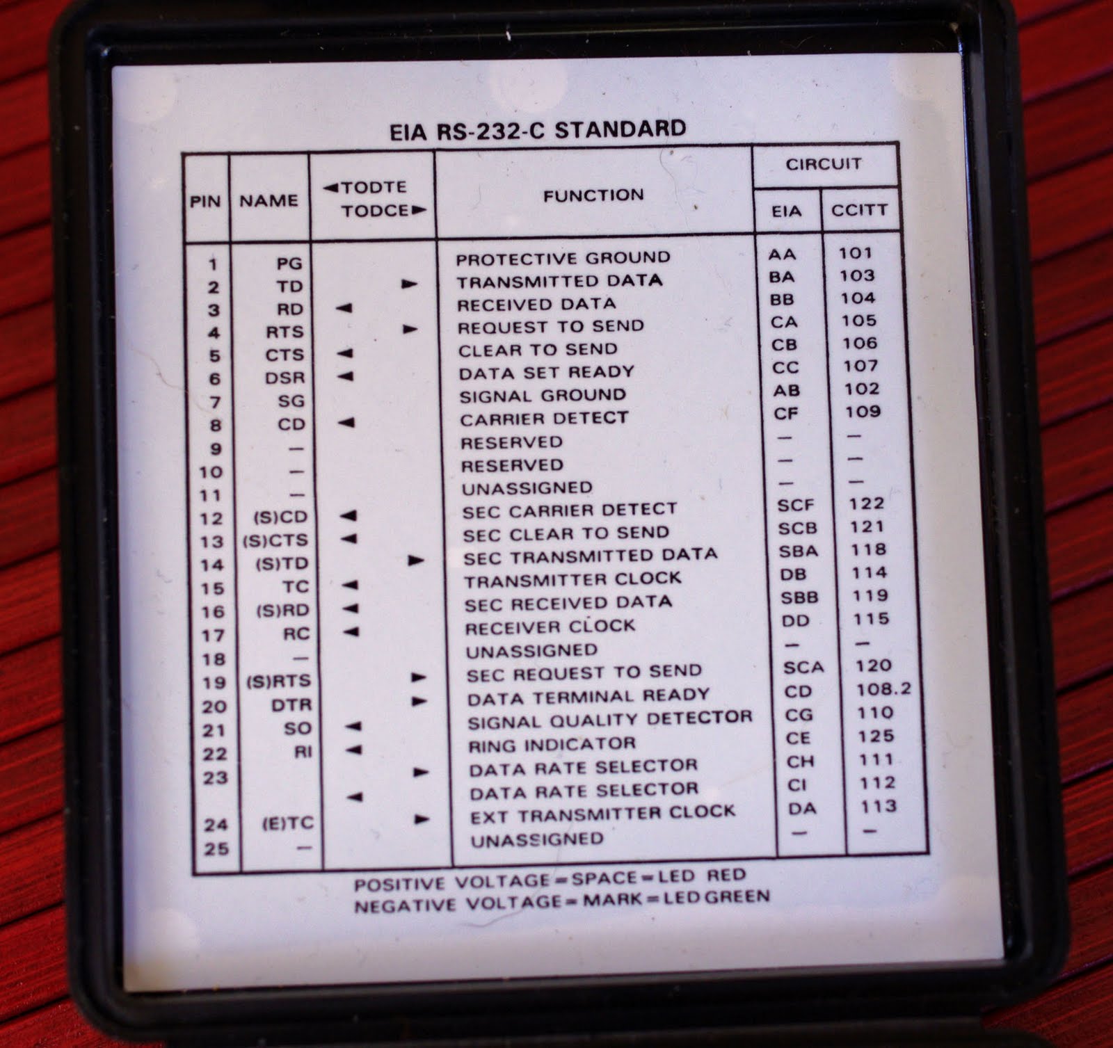
The functions of the various pins of the interface are listed in the lid of the unit for ease of reference. (This is the essence of the functional specification of RS-232-C.)
The picture above (when enlarged) not only lists the names of the pins, but also identifies the direction of the signal. The two endpoints are labelled DTE and DCE. DTE is an abbreviation for
data terminal equipment. The DTE may be a dumb terminal, but in most interesting applications the 'terminal' is really a computer. DCE used to indicate
data communications equipment, such as modems. However, it was changed to stand for
data circuit-terminating equipment - that is, it referred to the sort of thing that one would attach to the end of the telecommunications company's circuit, such as a modem.
One needs one further historical note to fully appreciate the specification: in the very old days modems were referred to as
datasets. Therefore line 6 (DSR,
data set ready) in modern language would have been called
modem ready or something similar.
To consider the (procedural) operation of the interface assume a DTE (such as a PC) wants to send a byte to a DCE (such as a modem). The DTE uses line 20 (DTR,
data terminal ready) to signal the DCE that it is ready. The DCE uses line 6 (DSR,
data set ready) to indicate to the DTR that it too is ready. The DTR then raises RTS (
request to send). If the DCE agrees, it raises CTS (
clear to send). The bits making up the byte are then transmitted via TD (
transmitted data). Note that there is not an equivalent set of signals to transmit data from the DCE to the DTE: the DCE raises CD (
carrier detect) when it sees data arriving on the phone line at the other end of the modem. Without waiting for permission, the DCE then sends the data to the DTE via RD (
received data).
Of course this asymmetry causes problems when one wants to connect two identical devices (such as two PCs). Problems also exist when devices do not fully support the standard. In the picture below pins 6 and 20 on the DTE side are jumpered. Therefore the moment the DTE says it is ready via line 20 (DTR) it gets a 'confirmation' (its own signal) via pin 6 (DSR), making it believe that the DCE is ready. Similarly one may jumper RTS and CTS together so that a
request to send will lead to an immediate
clear to send, without even involving the DCE. These are the type of tricks one would use to get a DCE to accept data even if it was not able to signal its own readiness to receive data.
One particular serial cable that was quite popular was the so called
null modem - a serial cable used to connect two computers (or, in general, two DTEs). RD on one plug would be connected to TD on the other, and vice versa. The DTR is connected to DSR and CD on the other end: when this PC wants to transmit, it raises DTR, and the other PC thinks that the 'modem' is ready,
and that data is arriving via it. (Similarly DTR on that end is connected to DSR and CD on this side). Finally, one could jumper RTS and CTS together on each side, so that either side can give itself permission to send. If this did not work (and it often did not) then it was time to reach for the breakout box. I remember a time when I had to connect a Univac 1100 mainframe to a Burroughs B20 micro via a serial cable. No matter what I did, I was unable to push communication speed above 300bps. And the serial interface on the mainframe cost more than what a typical car did...
Here is the breakout box with a matchstick as an indication of its size.