Asynchronous Transfer Mode (ATM) is a networking technology that routes cells (that is, small, fixed-size packets) of data from one end of a network to the other.
A link between any two switches is divided into multiple channels by using multiplexing. These virtual channel links are numbered with a number called a
virtual channel identifier (VCI). That is, any given physical copper cable, optical fibre or other link between two ATM switches consists of multiple (possibly thousands of) virtual channels. When a connection is established it is necessary to find a series of virtual channels (each obviously on a physical link) that connects the two endpoints of the connection. A series of virtual channel links are known as a
virtual path, which is identified by a
Virtual Path Identifier (VPI). The VPI and VCI are fields in the header of a cell. Whenever a cell arrives at a switch, the switch in essence performs a table lookup using the VPI/VCI pair, as well as the interface on which the cell arrived. From the table it determines the VPI and VCI that should be used by the next switch; it replaces the VPI/VCI fields in the cell header and then forwards the cell through the appropriate network interface.
Given the description above we can now look at an ATM switch. The switch we will use is FORE System's ForeRunner ASX 200. It looks as follows:
 |
| ForeRunner ASX 200 |
Just below the unit's name are four slots, labelled A, B, C and D. The network media will be connected to the modules in these slots. Slot A is currently empty with a blank plate covering it. Slots C and D contain identical modules and slot C contains a different module. We will return to these modules later.
Just underneath these four slots is a 'drawer' that contains the
switch board or
switch fabric. It contains the VPI/VCI lookup tables. However, doing a simple table lookup for every cell won't enable the switch to maintain the speed it should. Therefore the
fabric is more than just a set of tables.
Below the switch board is another 'drawer' which is the processor (or computer) that controls the switch. It is therefore aptly called the
switch control processor (SCP). It contains a SPARC processor, some memory, control logic and a hard disc. On the front panel of the processor are a couple of connectors. The two serial ports may be used to connect a terminal to the switch. One may then interact with the SCP via the terminal. There are two ports so that one may connect a local terminal, as well as a remote terminal via a modem to the SCP. The Ethernet connector enables one to connect the SCP to a network (via an Ethernet MAU) and then manage the switch via the network. In addition the front panel contains a reset facility and some status LEDs.
In the next picture the 'drawer' containing the SCP has been partially opened. (Also note that the network modules that were in slots B, C and D have been removed.)
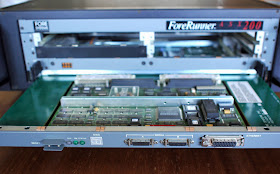 |
| Switch with SCP partially opened. |
When the SCP is removed fully it is possible to see the processing ICs, as well as the hard disc at the rear.
 |
The SCP from above. Note the hard disc towards the rear
and the processor below the transparent glass. |
The SPARC processor glistens like a jewel on the SCP.
 |
| A closer view of the Sun SPARC processor |
As noted above, the 'drawer' just above the SCP contains the switching fabric. The next picture shows it removed from the chassis.
 |
| The switching fabric removed from the chassis. |
The switching fabric contains the slots into which the network modules may be plugged. Note, in particular, the four sockets at the rear of the slots for these modules. The remainder of the switching fabric consists of ICs that facilitate the connection of the interfaces on the network modules with one another as specified by its current VPI/VCI tables.
Now that the supporting infrastructure has been discussed the four slots that contain network modules can be revisited. This switch can maintain a speed of 2.5Gbps. The capacity is spread equally over the four slots, meaning that every slot can contain a module that will be able to communicate at a sustained 2.5Gbps/4 = 625Mbps. One may either install a module that uses all this bandwidth for a single high-speed medium, or one may install a module that distributes the capacity over several links. The module in slot B contains six (actually six transmit/receive pairs of) connections that each is able to maintain a speed of 625Mbps/6 = 105Mbps. The modules in slots B and D each has four connectors. Each connector should therefore be able to maintain a speed of 665Mbps/4 = 166Mbps.
The modules in slots B and D are labelled NM-4/155UTP5EC. Reading this label from the left identifies it as a (network) module with 4 ports each operating at 155Mbps over UTP category 5 cable. Somehow the EC indicates that it uses SONET framing (in contrast to a similar model that has only a C in this position and that uses SDH framing). The differences between the SONET and SDH standards are small, but technical and not important for the purposes of this museum. Note that the actual SONET/SDH speed used is 155.52Mbps.
 |
| The NM-4/155UTP5EC modules in slots B and D |
The network modules are designed to be easily removable. The next picture shows one of the modules partially removed.
 |
| An NM-4/155UTP5EC module partially removed. |
In fact, the switch was designed to enable hot swapping of these modules. If a module fails it may be removed from the switch and replaced by a similar module without affecting the rest of the network. The replaced module resumes operation as soon as the new module is plugged in.
 |
| An NM-4/155UTP5EC module viewed from the top. |
The other module in the switch is an NM-6MM/125B is somewhat more of a conundrum, since I have been unable to find detailed information about it, and its naming convention is different from other modules. It clearly is a module with 6 optical fibre ports. In other modules MM indicates that it uses multimode optical fibre (but the MM usually follows the slash, rather than precedes it). The 125 in the context of fibre may mean 125µm fibre, but this is purely guessing.
 |
| The NM-6MM/125B module in slot C (as well as the covered empty slot A). |
The next picture contains a slightly closer view of the NM-6MM/125B module.
 |
| The NM-6MM/125B |
Turning one the power lets the switch erupt in colour as only network devices can.
 |
| ForeRunner ASX 200 powered up |
The final picture shows the switch, an 18" ruler (underlining the fact that the switch is intended for a 19" cabinet), as well as the network modules outside the chassis.
 |
| ForeRunner ASX 200 with network modules. |
The ForeRunner ASX 200 was built by FORE Systems. FORE Systems was established in 1990 by four researchers from Carnegie Mellon University, Francois Bitz, Onat Menzilcioglu, Robert Sansom, and Eric Cooper, whose first letters from their first names were used to form the acronym FORE. FORE Systems soon became a player to be reckoned with in the telecommunications space - in particular due to their excellent ATM switches. In 1999, a British company, General Electric Company, bought FORE to put itself in a stronger position in the US. Long before this, in 1968, General Electric bought Marconi Wireless Telegraph Company. Long story short: In 2003 General Electric Company decided to change their own name to Marconi Corporation. In 2005 most of Marconi (including what used to be FORE) was sold to Ericsson.


