25 October 2011

A brief history of the cloud - as I recall


Once upon a time wide area networks (WANs) had topologies.  Lines (or sometimes waves) would connect the various nodes or sites.  And whether the WAN was spread across a campus or across a country, one could somehow represent the network using a map.


The lines that crisscrossed the country typically belonged to some national operator, but the company that rented it sort of 'owned' it and could use (or waste) the available bandwidth in whatever way it wished.  The problem, of course, was that while they constantly had the bandwidth available, they also constantly paid for the bandwidth.  For busy lines this was sometimes cost-effective.  For occasional connections one could consider dial-up links that would only establish the link when necessary.  However, in many cases (including frequent but brief communication) a permanent link where one only paid for what was actually transmitted would be a better solution.

A concomitant problem occurred where the links spanned national boundaries.  Within a country a line could be leased from the national operator, but there was no 'international' operator from whom one could lease a line from, say, Cape Town to Cairo.

The solution to both these problems came in the form of PDNs, which is an acronym for public data networks and/or packet data networks.  The networks were public in the sense that they were originally still operated by the national operator and any company (or wealthy individual) could connect to the PDN.  They were packet-based because messages were split into packets and packets were intermingled with other users' packets on the same wires, but routed to the correct destinations where the messages were reassembled.

The first incarnation of these PDNs was X.25 networks.  In those days the South African Post Office was the national network operator in South Africa, and the national leased line infrastructure known as SAPONET (for South African Post Office Network).  When the (then) new packet-oriented X.25 network was introduced it was called SAPONET-P.  The old SAPONET network was renamed to SAPONET-C to emphasise that it used circuit switching.

One problem that arose with these new networks was that one did not know where the links were.  However, one of the major benefits of these networks was that one did not need to know where the links were: It was the operator's responsibility to route packets from their origins to their destinations.  It was no longer the user's problem if its link between its Cape Town and Johannesburg offices was down.  One transmitted a packet into the network and it was then the operator's responsibility to get it to its destination - using whichever route the operator preferred.  The network became a fuzzy entity where users could be blissfully unaware of how it was configured or operated internally.

Textbooks from the late 1980s soon began representing such WANs as clouds.  Exactly how 'realistic' the cloud was drawn depended on the preferences of the author or the publisher.  Similarly, anyone who presented a lecture on networking had to draw some clouds during the lecture, which were often drawn with great flair.


The X.25 cloud was interesting in part because of the set of standards that operated outside, inside, across and between clouds.  The book in the bottom left quadrant of the picture above (Uyless D Black, Computer Networks: Protocols, Standards, and Interfaces, 2nd ed, 1993) nicely illustrates where these standards were 'located'.  Note, in particular, X.75 that enables different national networks to be interconnected - linking one country's cloud to that of another country.

Various other incarnations of PDNs followed, including frame relay and ATM.  While some netwoks using these technologies still exist (and are often actively used) the trend is to move to TCP/IP.  Over time most of the clouds converged and became a single cloud known as the Internet.  And for a while the Internet was a cloud - the cloud - but nobody thought it was a big deal.

But what was changing was who was communicating with whom.  In the days of X.25 a company typically communicated with its branches.  In some cases some companies did communicate with others.  Initial bank networks, for example, connected a bank's branches with its central offices.  However, different banks for a long time after they began using networks still communicated in a primitive manner.  In South Africa the Automated Clearing Bureau (ACB) was established in 1972.  Banks would send tapes with details of their transactions every evening to the ACB, where the tapes where processed and it was (automatically) determined how much the various banks owed one another.  In the early 1980s a few brave banks in South Africa connected directly to one another's networks, but most preferred to connect via a central service that was established by the banks and called SASWITCH.

The 1990s saw terms such as B2B (business to business) and B2C (business to customer) emerge to focus on this changing landscape.  Eventually services like eBay and Webmail arguably implemented 'C2C' (customer to customer) networks, although I have never seen the term C2C used in a technical context.  Web 2.0 - with its user-provided content - is another example of C2C communication, although its protagonists probably did not foresee the extent to which these 'users' would actually be C2C (commodity to commodity) communicators in a twisted post-modern world where the consumer has become the commodity and vice versa.

Initially these changing communication patterns had little impact on the cloud(s).  The business (or consumer) was merely communicating with the other business (or consumer) via the cloud using the same old (or, at least, similar) protocols that were used earlier.  But where the primary problem earlier was to communicate between specific places (such as, say, Johannesburg and Bloemfontein), the focus changed to get to information or a service irrespective of where it was.  The business in Bloemfontein can host its Web presence at an ISP in Cape Town - and then move it to an ISP in Pretoria without users knowing or noticing (unless they wish to).

I remember the strange experience many years ago when I phoned AT&T's helpdesk in Johannesburg, but got the distinct impression that the call was answered somewhere in Europe (from the accent of the person who answered the call, the latency on the line and some other clues).  In fact, call-centres were one of the early services to be relocated to anywhere it was convenient.  The local 'call-centre' would consist of a telephone number and the necessary circuitry to forward the call as voice data over the network to the real call centre located where labour and/or facilities where cheaper.  In the simplest cases it meant that a call-centre was not required to be everywhere, but local numbers could make it appear that help was only a local call away.

In the same way any service that primarily provided information or digital goods could be located or relocated anywhere.  In the simplest cases companies' Web and email servers no longer needed to be on-site; they could be managed by a service provider anywhere on the network.  An entire industry came into being to provide such services, and the number and variety of services increased.  Initially the companies offering these services were simply on the 'other side' of the cloud: one knew where they were.  One still used them with the same old protocols that entered the cloud at some local ingress point and exited the cloud at an egress point at the destination - and the response used the same mechanism in reverse.  But quickly things became fuzzier.  It is now much harder to say where, say, google.com or f.root-servers.net is.  At the time of writing many South African readers are probably unaware that much of their communication with Google actually occurs with a Google cache in Cape Town, and that many of their DNS requests (on root level) are resolved by a root name server in Johannesburg, whereas those using the Internet elsewhere in the world when talking to these 'same' entities are talking to physical machines located on other continents.  And all of this happens transparently to the user.  The information no longer comes from the other side of the cloud - it comes from somewhere inside the cloud; it comes from who knows where.


A brief description of the history of clouds should also consider what one uses in the cloud: Is it data, an application, a platform, infrastructure, or something else?  However, this post is already stretching the limits of brevity, and those facets of the history of clouds will have to wait for a later post.
"I've looked at clouds from both sides now,
From up and down, and still somehow,
It's cloud illusions I recall,
I really don't know clouds, at all."

11 September 2011

An ATM switch

Asynchronous Transfer Mode (ATM) is a networking technology that routes cells (that is, small, fixed-size packets) of data from one end of a network to the other.

A link between any two switches is divided into multiple channels by using multiplexing.  These virtual channel links are numbered with a number called a virtual channel identifier (VCI).  That is, any given physical copper cable, optical fibre or other link between two ATM switches consists of multiple (possibly thousands of) virtual channels.  When a connection is established it is necessary to find a series of virtual channels (each obviously on a physical link) that connects the two endpoints of the connection.  A series of virtual channel links are known as a virtual path, which is identified by a Virtual Path Identifier (VPI).  The VPI and VCI are fields in the header of a cell.  Whenever a cell arrives at a switch, the switch in essence performs a table lookup using the VPI/VCI pair, as well as the interface on which the cell arrived.  From the table it determines the VPI and VCI that should be used by the next switch; it replaces the VPI/VCI fields in the cell header and then forwards the cell through the appropriate network interface.

Given the description above we can now look at an ATM switch.  The switch we will use is FORE System's ForeRunner ASX 200.  It looks as follows:

ForeRunner ASX 200

Just below the unit's name are four slots, labelled A, B, C and D.  The network media will be connected to the modules in these slots.  Slot A is currently empty with a blank plate covering it.  Slots C and D contain identical modules and slot C contains a different module.   We will return to these modules later.

Just underneath these four slots is a 'drawer' that contains the switch board or switch fabric.  It contains the VPI/VCI lookup tables.  However, doing a simple table lookup for every cell won't enable the switch to maintain the speed it should.  Therefore the fabric is more than just a set of tables.

Below the switch board is another 'drawer' which is the processor (or computer) that controls the switch.  It is therefore aptly called the switch control processor (SCP).  It contains a SPARC processor, some memory, control logic and a hard disc.  On the front panel of the processor are a couple of connectors.  The two serial ports may be used to connect a terminal to the switch.  One may then interact with the SCP via the terminal.  There are two ports so that one may connect a local terminal, as well as a remote terminal via a modem to the SCP.  The Ethernet connector enables one to connect the SCP to a network (via an Ethernet MAU) and then manage the switch via the network.  In addition the front panel contains a reset facility and some status LEDs.

In the next picture the 'drawer' containing the SCP has been partially opened.  (Also note that the network modules that were in slots B, C and D have been removed.)

Switch with SCP partially opened.
When the SCP is removed fully it is possible to see the processing ICs, as well as the hard disc at the rear.

The SCP from above.  Note the hard disc towards the rear
and the processor below the transparent glass.
The SPARC processor glistens like a jewel on the SCP.

A closer view of the Sun SPARC processor
As noted above, the 'drawer' just above the SCP contains the switching fabric.  The next picture shows it removed from the chassis.

The switching fabric removed from the chassis.
The switching fabric contains the slots into which the network modules may be plugged.  Note, in particular, the four sockets at the rear of the slots for these modules.  The remainder of the switching fabric consists of ICs that facilitate the connection of the interfaces on the network modules with one another as specified by its current VPI/VCI tables.

Now that the supporting infrastructure has been discussed the four slots that contain network modules can be revisited.  This switch can maintain a speed of 2.5Gbps. The capacity is spread equally over the four slots, meaning that every slot can contain a module that will be able to communicate at a sustained 2.5Gbps/4 = 625Mbps.  One may either install a module that uses all this bandwidth for a single high-speed medium, or one may install a module that distributes the capacity over several links.  The module in slot B contains six (actually six transmit/receive pairs of) connections that each is able to maintain a speed of 625Mbps/6 = 105Mbps.  The modules in slots B and D each has four connectors.  Each connector should therefore be able to maintain a speed of 665Mbps/4 = 166Mbps.

The modules in slots B and D are labelled NM-4/155UTP5EC.  Reading this label from the left identifies it as a (network) module with 4 ports each operating at 155Mbps over UTP category 5 cable.  Somehow the EC indicates that it uses SONET framing (in contrast to a similar model that has only a C in this position and that uses SDH framing).  The differences between the SONET and SDH standards are small, but technical and not important for the purposes of this museum.  Note that the actual SONET/SDH speed used is 155.52Mbps.

The NM-4/155UTP5EC modules in slots B and D
The network modules are designed to be easily removable.  The next picture shows one of the modules partially removed.

An NM-4/155UTP5EC module partially removed.
In fact, the switch was designed to enable hot swapping of these modules.  If a module fails it may be removed from the switch and replaced by a similar module without affecting the rest of the network.  The replaced module resumes operation as soon as the new module is plugged in.

An NM-4/155UTP5EC module viewed from the top.
The other module in the switch is an NM-6MM/125B is somewhat more of a conundrum, since I have been unable to find detailed information about it, and its naming convention is different from other modules.  It clearly is a module with 6 optical fibre ports.  In other modules MM indicates that it uses multimode optical fibre (but the MM usually follows the slash, rather than precedes it).  The 125 in the context of fibre may mean 125µm fibre, but this is purely guessing.

The NM-6MM/125B module in slot C (as well as the covered empty slot A).
The next picture contains a slightly closer view of the NM-6MM/125B module.

The NM-6MM/125B
Turning one the power lets the switch erupt in colour as only network devices can.

ForeRunner ASX 200 powered up
The final picture shows the switch, an 18" ruler (underlining the fact that the switch is intended for a 19" cabinet), as well as the network modules outside the chassis.

ForeRunner ASX 200 with network modules.
The ForeRunner ASX 200 was built by FORE Systems.  FORE Systems was established in 1990 by four researchers from Carnegie Mellon University, Francois Bitz, Onat Menzilcioglu, Robert Sansom, and Eric Cooper, whose first letters from their first names were used to form the acronym FORE.  FORE Systems soon became a player to be reckoned with in the telecommunications space - in particular due to their excellent ATM switches.  In 1999, a British company, General Electric Company, bought FORE to put itself in a stronger position in the US.  Long before this, in 1968, General Electric bought Marconi Wireless Telegraph Company.  Long story short: In 2003 General Electric Company decided to change their own name to Marconi Corporation.  In 2005 most of Marconi (including what used to be FORE) was sold to Ericsson.

13 August 2011

Beltel

In the late 1970s Bulletin Board Systems (BBSs) emerged.  They were systems maintained by computer enthusiasts who referred to themselves as SysOps (system operators).  A SysOp would provide the BBS and link it via one or more modems to the telephone service.  Other users could then dial into the BBS and leave messages for other users, retrieve messages and upload or download software and other files.

Soon after that telecomms companies started experimenting with similar technology.  BBSs initially allowed users in the local BBS community to exchange information and files.  In contrast, the telecomms companies could convince other businesses to link to their systems as service providers.  The telecomms companies also had billing arrangements with consumers in place and therefore were able to facilitate selling of information and software and ensure that payment flowed from buyers to sellers.

The systems adopted by telecomms companies were generally known as Videotext systems.  In the UK the videotext system was known as Prestel; in many other countries systems were developed that were to a greater or lesser degree based on Prestel.  In 1986 the Sout African version, known as Beltel, was introduced by the South African Post Office (who then also operated the country's phone system).  Like other Videotext systems, it allowed communication via a 40-column 'terminal'; it also allowed chunky block graphics where every character could be divided into four 'pixels'.

Back then the Internet was still a scientific/academic network.  In contrast, the Videotext services were commercial and provided a platform for e-commerce to develop.  Below is a picture of the 1996 Services Directory containing about 20 pages of lists of businesses that were connected to Beltel, waiting for business from Beltel users.

In addition to the directory of service providers, the directory also provided some other information.  Page 2, for example, answered the question: What is Beltel?
Page 25 listed the Beltel tariffs.
To use the system one either used a dedicated terminal (known as a Minitel) to connect to the system, or one used an ordinary PC with special software installed.  The software used with Beltel was known as PCbel and came on a floppy or, later, on what is in South Africa known as a stiffie.
I just placed the PCbel diskette depicted above in my PC and it still seems readable (but not without some complaints from the system).  The floppy contains two files:

  • install.exe, which is 18368 bytes long and dated 22 January 1993 
  • newpcbel.exe , which is 168925 bytes long and dated 27 January 1993 

The primary use of Beltel for many of us was online banking.  Years before Internet banking was 'invented' we banked online via Beltel.  Here is an example of an online payment to a supplier.
The printout is, in essence, a screenshot of what appeared on my screen when I made the payment.  Note the width of 40 columns and height of 24 rows.  Note the menu system used for navigation: On this particular screen one could press I for the index, E for the end (of interacting with this particular information supplier) and so on.  In the top right hand corner is the amount I had spent thus far: 0,0c - that is, nothing.  Banks did not charge for using their services via the Beltel billing system; they rather levied charges directly from the customer's account with them.

The printout above is dated 28 February 1999, which means it dates from fairly late in Beltel's history.  As the Internet developed the use of Videotext systems declined and eventually were withdrawn.  My bank 'forced' me to move to Internet banking by increasing its monthly fee for Beltel banking to an exorbitant amount, while Internet banking was offered at a low fee (and eventually free).

Earlier in the history of Beltel it was assumed that few users had printers at home.  When one joined Beltel banking the bank typically gave one a folder in which to keep a record of one's transactions.  First National Bank called their Beltel bank Videobank.  Below is my folder for such record keeping.  Page 1 is unfortunately missing.  The first entry on page 2 is dated 29 December 1993.  Extrapolating to page 1 suggests that I started using online banking around August 1993 - about 18 years prior to this post.

01 August 2011

RS-232-C breakout box

In years gone by the primary interface used for communicating data was the serial interface.  Its name stems from the fact that data was communicated one bit at a time, one bit after another - that is, serially.  The alternative was a parallel interface, where all the bits making up, say, a byte would be communicated in parallel.  In principle a parallel interface is faster, but also more expensive since it needs one circuit for every bit, whereas serial needs a single circuit to communicate one bit at a time.  Most current data communication technologies use serial transmission: USB, Ethernet via coax, Firewire, Ethernet via UTP at 100Mbps or less, etc.  Where the water is muddied somewhat is at the faster communication rates: Ethernet via UTP at gigabit speeds tend to transmit two bits in parallel...

For many, many years the most popular standard was RS-232 (that is Recommended Standard number 232 of the Electronics Industries Association or EIA).  The standard was issued in a number of versions, with B, C and D suffixed to the later versions.  However, industry did not see the need to proceed beyond the C-version, and RS-232-C was therefore the standard used in practice.

Despite being a standard one often spent countless hours trying to get two pieces of equipment to talk to one another.  Some of the problems stemmed from the fact that few vendors' products really complied with the standard.  Other problems often stemmed from the way the communication interfaces were used:  The standard really specifies a way to interface a computer to a peripheral unit.  Clearly, the more interesting option was to get two computers to talk to one another.

Given such a myriad of problems every self-respecting data communication fan had a breakout box.
The picture above illustrates such a breakout box.  It contains two plugs that enable it to be inserted into a serial link.  A number of LEDs allow one to observe the voltage level on some of the wires.  A number of switches allow one to make or break a specific connecting line between the two communicating units.  A number of sockets allow one to jumper one wire to another.  These aspects are illustrated in more detail below.

The standard specifies four facets of serial communication: mechanical, electrical, functional and procedural.  The first, mechanical, recommends that a 25-pin DB-25 plug should be used.  This breakout box complies with that specification.  On the box itself a female DB-25 socket is available.
Linked via a ribbon cable on the other side of the box is a male DB-25 plug.
An obvious question is why a serial interface needs 25 pins (and 25 wires connecting them).  The answer lies in the fact that the standard contains some wonderful bells and whistles, such as the ability to communicate via a secondary serial channel without interrupting the communication taking place via the primary serial link.

Industry soon responded to this extravagance by ignoring most of the 'unnecessary' pins, and replacing the DB-25 plug and socket with a DB-9 plug and socket.  This illustrates just one way in which vendors used their own versions of standards.  (Also, technically, it was a DE-9, but everybody called it a DB-9.)

The breakout box, however, supports all 25 connections.  Three banks of eight DIP switches enable one to make or break the corresponding connection.  Line 1, protective ground, is permanently connected - the connection status of the remaining 24 depends on the setting of a DIP switch.
Only the most important lines are wired through a LED.  The electrical specification of RS-232 states that about -15 volt indicates a 1 and about +15 volt a 0.  (In fact, anything below -3V indicates a 1, and anything above +3V a 0.)  The LEDs on this particular breakout box glow green for a negative voltage (1) and red for a positive voltage (0).

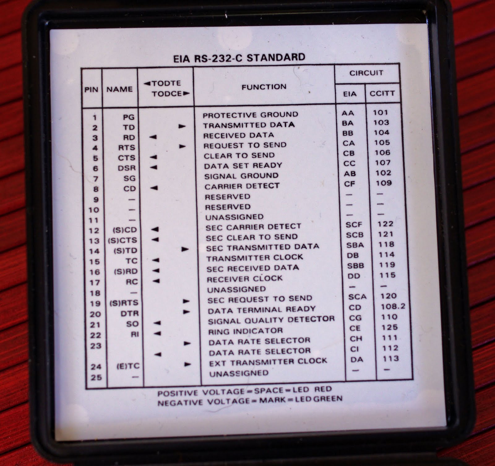
The functions of the various pins of the interface are listed in the lid of the unit for ease of reference.  (This is the essence of the functional specification of RS-232-C.)
The picture above (when enlarged) not only lists the names of the pins, but also identifies the direction of the signal.  The two endpoints are labelled DTE and DCE.  DTE is an abbreviation for data terminal equipment.  The DTE may be a dumb terminal, but in most interesting applications the 'terminal' is really a computer.  DCE used to indicate data communications equipment, such as modems.  However, it was changed to stand for data circuit-terminating equipment - that is, it referred to the sort of thing that one would attach to the end of the telecommunications company's circuit, such as a modem.

One needs one further historical note to fully appreciate the specification: in the very old days modems were referred to as datasets.  Therefore line 6 (DSR, data set ready) in modern language would have been called modem ready or something similar.

To consider the (procedural) operation of the interface assume a DTE (such as a PC) wants to send a byte to a DCE (such as a modem).  The DTE uses line 20 (DTR, data terminal ready) to signal the DCE that it is ready.  The DCE uses line 6 (DSR, data set ready) to indicate to the DTR that it too is ready.  The DTR then raises RTS (request to send).  If the DCE agrees, it raises CTS (clear to send).  The bits making up the byte are then transmitted via TD (transmitted data).  Note that there is not an equivalent set of signals to transmit data from the DCE to the DTE: the DCE raises CD (carrier detect) when it sees data arriving on the phone line at the other end of the modem.  Without waiting for permission, the DCE then sends the data to the DTE via RD (received data).

Of course this asymmetry causes problems when one wants to connect two identical devices (such as two PCs).  Problems also exist when devices do not fully support the standard.  In the picture below pins 6 and 20 on the DTE side are jumpered.  Therefore the moment the DTE says it is ready via line 20 (DTR) it gets a 'confirmation' (its own signal) via pin 6 (DSR), making it believe that the DCE is ready.  Similarly one may jumper RTS and CTS together so that a request to send will lead to an immediate clear to send, without even involving the DCE.  These are the type of tricks one would use to get a DCE to accept data even if it was not able to signal its own readiness to receive data.

One particular serial cable that was quite popular was the so called null modem - a serial cable used to connect two computers (or, in general, two DTEs).  RD on one plug would be connected to TD on the other, and vice versa.  The DTR is connected to DSR and CD on the other end: when this PC wants to transmit, it raises DTR, and the other PC thinks that the 'modem' is ready, and that data is arriving via it.  (Similarly DTR on that end is connected to DSR and CD on this side).  Finally, one could jumper RTS and CTS together on each side, so that either side can give itself permission to send.  If this did not work (and it often did not) then it was time to reach for the breakout box.  I remember a time when I had to connect a Univac 1100 mainframe to a Burroughs B20 micro via a serial cable.  No matter what I did, I was unable to push communication speed above 300bps.  And the serial interface on the mainframe cost more than what a typical car did...

Here is the breakout box with a matchstick as an indication of its size.